GE Master II Receiver:
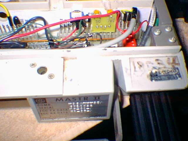
The unit has also had an NHRC Squelch/Volume control board installed to replace the external control head.
In the upper right of the photo below the two yellow pots can be seen that are used to adjust the Volume and Squelch set points. You can see that this board plugs into the connector just about the red test jack.

The local speaker has been retained however, with an 8 ohm 20 watt non-inductive resistor and DPDT toggle switch installed in the speaker cabinat so that the local speaker can be muted and yet a load be kept on the audio output so that it does not oscillate.
The receiver strip has been tuned up in accordance with the GE alignment specs. Furthermore the unit was partially disasembled so that the chassis mounted SO-239 connector could be used by routing the double shield cable RCA connector from the PA T/R relay (see below) in the PA section into the receiver section. This aided in the ability of the system to operate without desense. Previously, as in most conversions, a short lenght of cable was fished out from the receiver section and was wrapped around a toroid to keep RF from running back into the receiver on the shield.

Here is the direct connection to the receiver strip from the chassis mounted SO-239.

The volume has been preset for a comfortable listening level to the local speaker and then fed into the controller for transmit audio, being adjusted within the controller. Thus the audio being used at present is squelched, pre-emphazised and has had any sub-audible tone content removed by the standard EIA tone reject filter in the Master II.
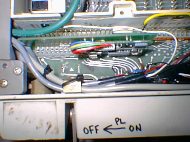
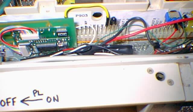
The GE Channel Guard board can no longer be used as the installation of internal DPDT toggle switches that protrude through the front of the normal 40 pin connector prevent such. At any rate a Communications Specialist TS64MASTRII encode/decode board has replaced it. A PL disable toggle switch has been installed that can be used with the cover in place or removed.
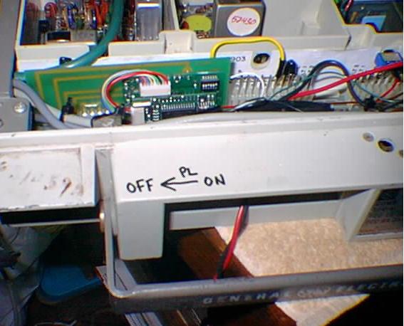
CTCSS Encode/Decode:
The RC-1000 is directly interconnected to the Communications Specialties TS-64MSTII CTCSS Encode/Decode board inside the Master II. While a PL tone of 131.8 Hz (tone 3B) is used to activate the repeater when enabled, those without PL who have DTMF capabilities can enter "*32" which will temporarily take the repeater out of PL until 30 seconds of inactivity has elapsed.
It is planned that a 131.8 Hz tone will always present on the output at some point for those who wish to run full CTCSS squelch all the time. However at times the system will operate in the following CTCSS (PL) modes:
NO CTCSS (Normal at first)
No CTCSS to access with PL ENCODE on transmit at all times (Normal as some point)
CTCSS ENCODE/DECODE (When band conditions warrant)
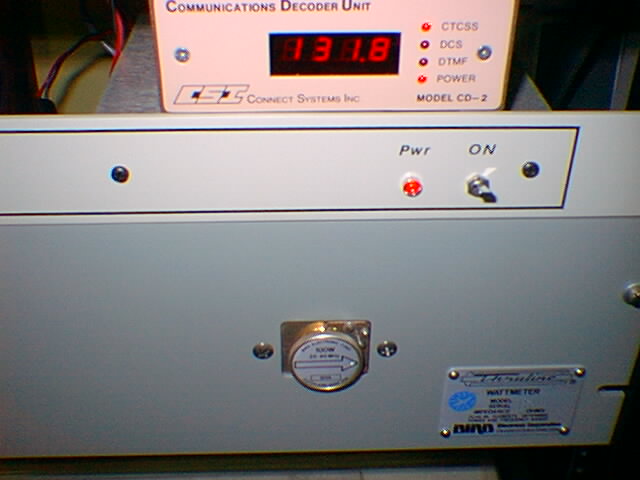
For the purpose of visual display at the sight during testing and system monitoring and more importantly to provide data to the control computer, a Connect Systems Inc, CD-2 CTCSS, DCS and DTMF decoder unit with an RS-232 output is part of the system.

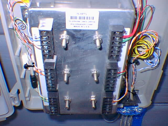
For the 911 Emergency Autopatch we have updated our phone system interconnect to include a PolyPhaser 6 line ligthening arrestor unit as seen below.
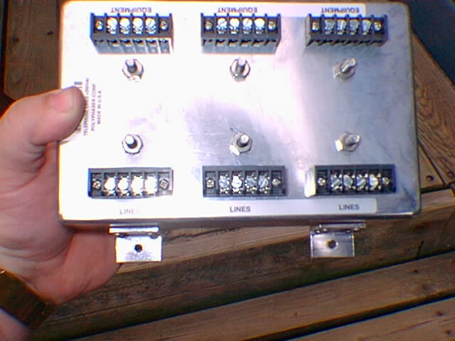
Here is the main egress for all the phone lines coming into the building.
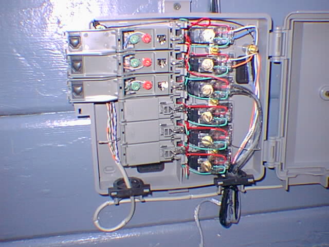
Here is the PolyPhaser unit installed in its own weather tight enclosure.

Entire contents Copyright © 1999-2001 by Stephen B. Hajducek, N2CKH. All Rights Reserved Worldwide.